
This page will work alongside the Raspberry Pi with Processing page, as I will be trying to learn about both platforms, and see the relative merits of each in different circumstances.
9: Understanding Ohm’s Law and Simple Circuit Design
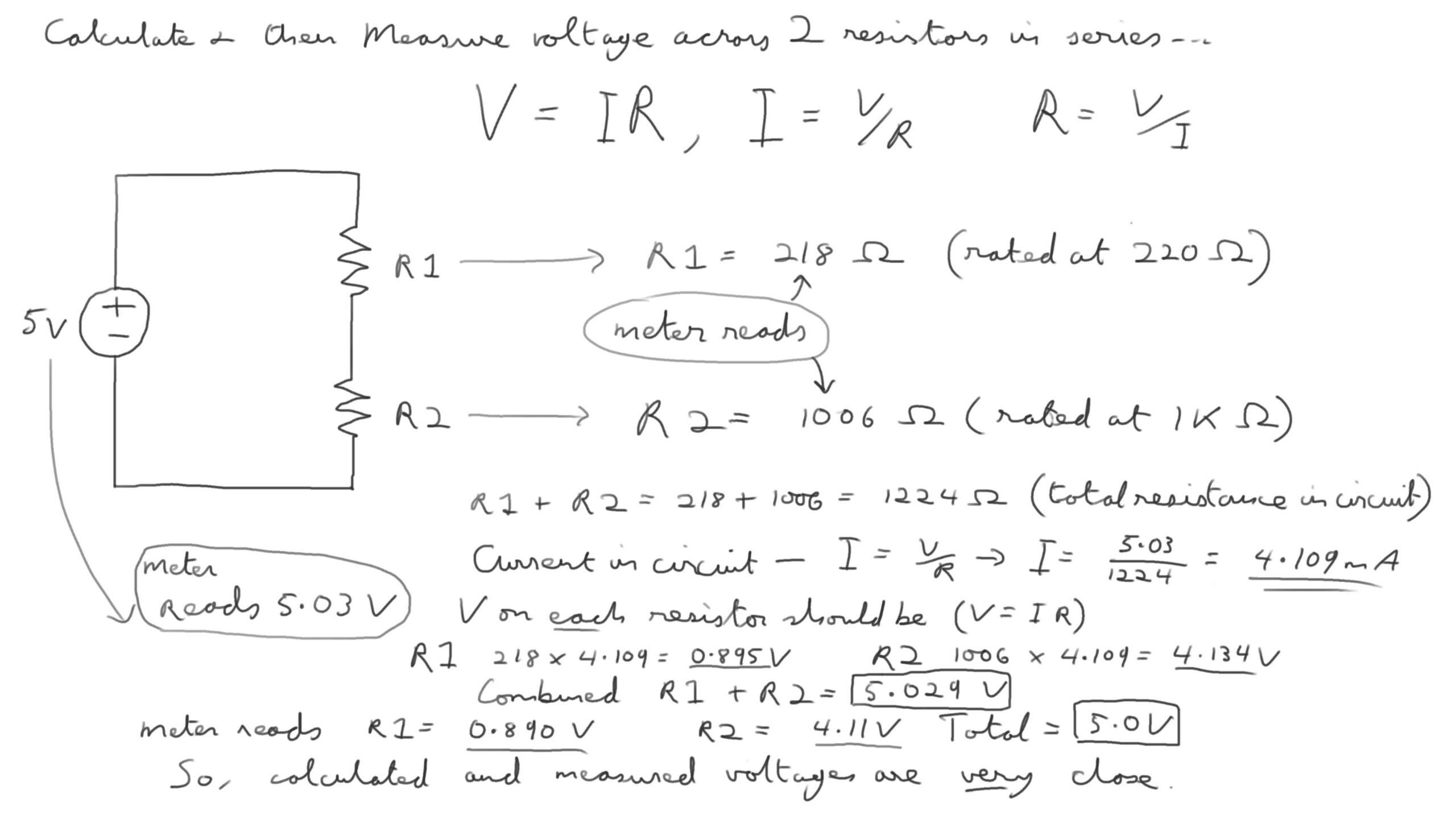
Using Ohm’s Law (V=IR), calculating the current in a simple cicuit with 2 different value resistors, then using that current to calculate the expected voltage across both resistors. Pic above shows that the expected and measured values matched up nicely. 5V power supply just taken from 5V pin of the Arduino, no coding needed.
10. analogRead() function
Circuit similar to that above, but now we take a jumper from the circuit back to a pin to have the Arduino measure the Voltage itself. To read analog inputs coming into the Arduino, we must use the Analog In pins (A0 to A4) as the as the regular pins or PWM (pulse width modulation) can’t do it.
Unlike the Pi, the Arduino uses a separate serial monitor to display information, which has to be called from the Tools menu. In the code, it needs to be initialised with the Serial.begin command. The analogRead() command returns a number from 0 to 1023, which is a scaled reading of 0 to 5V. We need to convert that to real voltage value with maths in the code, 5/1023 times the read value to get real voltage. After struggling to get the Arduino to read the same values as my voltmeter, I realised that the Arduino is always measuring the voltage from ground to the cable going to the analog in pin. Meaning with two resistors in series, you can only measure the one closest to ground, or both together. Conversely, the voltmeter allows you to measure the voltage on both or either resistors individually. Good to know.
12: Understanding Potentiometers
Again similar circuit to above, with the resistors replaced by a potentiometer. Code is basically the same. Reads nicely from 0 to 5V as you turn the potentiometer.
13: Understanding Arduino If Statements
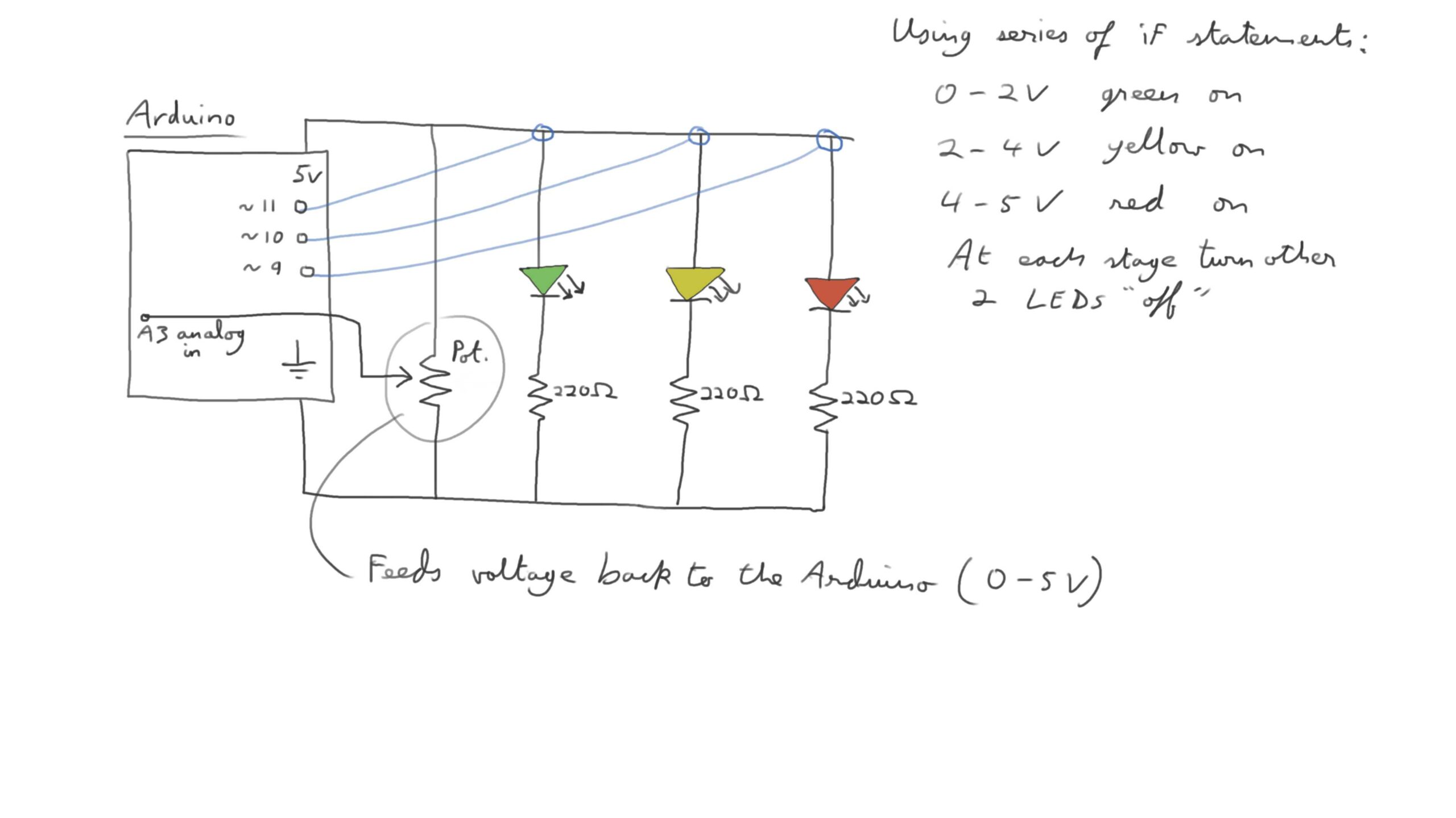
An introduction to if statements together with a potentiometer to turn on a series of “warning” LEDs as the voltage on the pot increases from 0 to 5V. Just needed to be careful to turn the other 2 LEDs off when they were not required to be on.
14: Dimmable LED Project
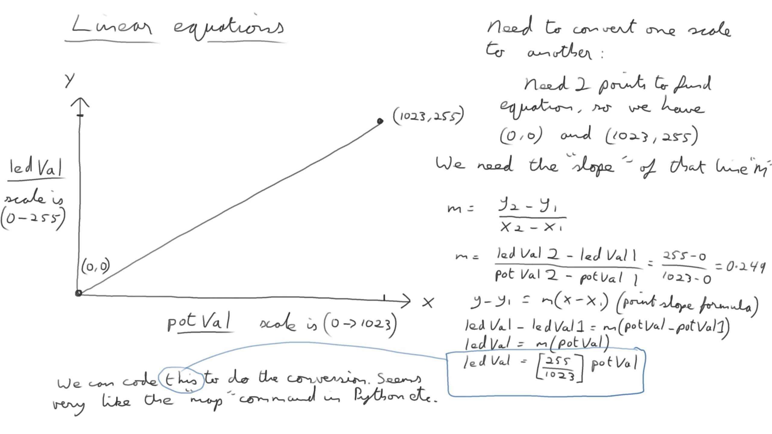
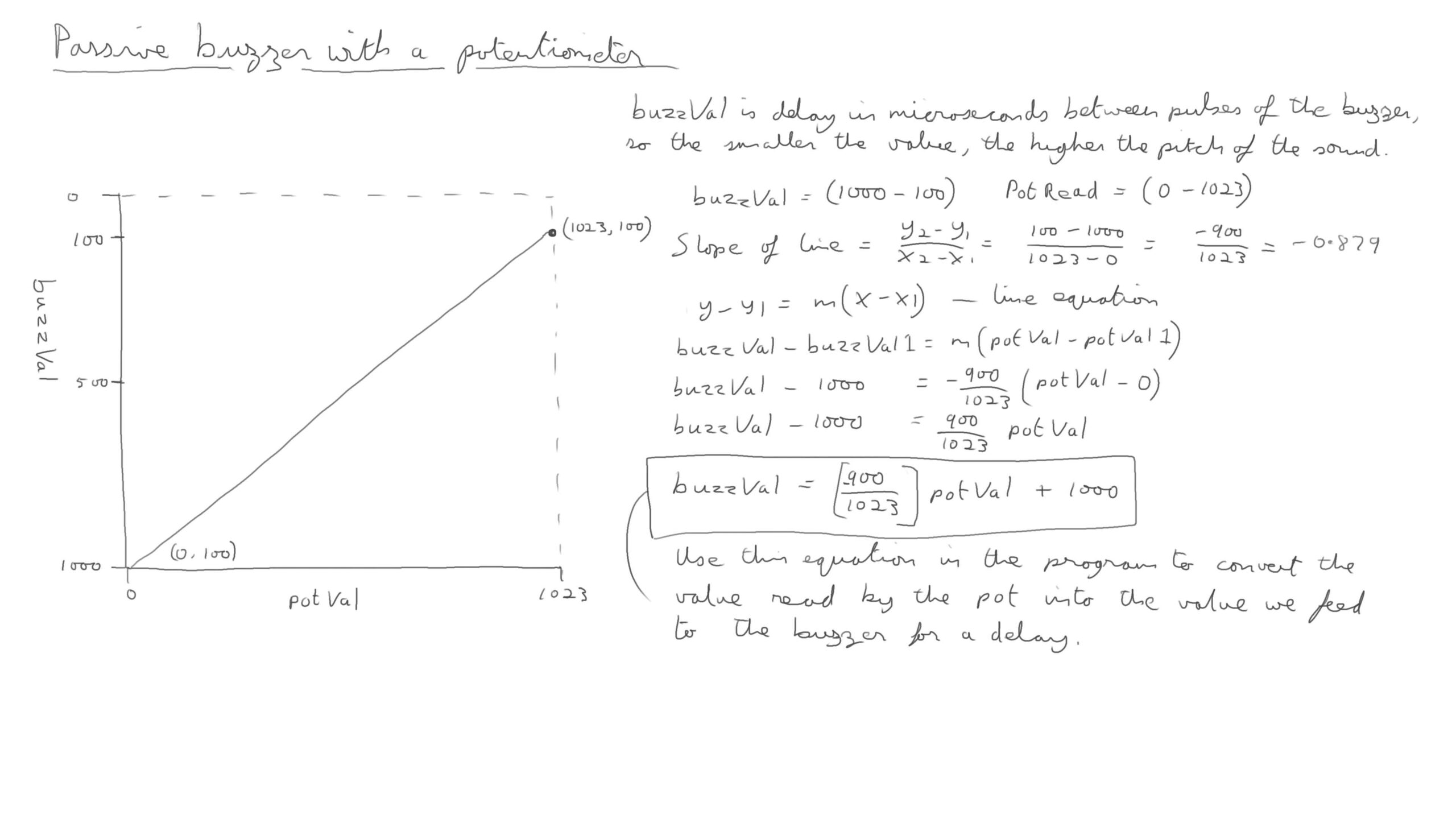
A simple circuit and program to read a value from a potentiomer and feed it from a PWM to a LED. This however needs a conversion from a scale of 1023 (what the analog in pin reads) to one of 255 (which the ) analogWrite command uses). The above pic shows how to mathematically work this out properly, which I’d long forgotten if I ever knew it. Finding the slope of the line and using the point slope formula is what it does, which seems to be just what the “map” function does in other languages.
17: Understanding Arduino While Loops
A series of exercises exploring for and while loops to control the circuit’s behaviour. This one has a potentiometer reading the voltage, and a pin connected to an LED. A while loop is used to only turn on the LED when over 3 volts is read from the pot. Easy to get caught out here – the pot’s voltage needs to be continuously read from within the while loop, otherwise it’ll get stuck looping in the one state, as it won’t know if the voltage has changed. The LED gets put to HIGH in the while loop if the condition is met, and the LOW state needs to be outside the while loop, within the void loop().
Also realised that the PWM pins can still be used to output digital HIGH or LOW. They seem to output HIGH when it hits 1 volt output.
18: Reading Numbers & Strings from the Serial Monitor
This uses the serial function to get the user to communicate with the Arduino, connected to a computer, via the serial monitor. In this case the user inputs an int which is then fed to an output pin to blink an LED on and off the required number of times. It can also read strings from the user. While the Arduino is waiting for the user, a while loop is used with the command while (Serial.available() == 0) As soon as the user inputs something it drops out of the loop and executes the code.
19: Reading Strings from the Serial Monitor
This one has 3 LEDS, red, green and blue connected to different pins. Using Serial.readString() we get a colour as a string from the user. A set of if statements switches on the relevant LED. Again a while loop (Serial.available() == 0) waits until the user does something. Also, the if statements have an additional option in case the user types in the colour with a capital letter if (myColour == “red” || myColour == “Red”)
20: Understanding RGB LED’s
Again reads strings from the user but this time to light up an RGB LED in either red, green or blue.
21: Understanding and Mixing Primary Colors with an RGB LED
Same circuit as above but the digitalWrite() commands now are analogWrite() commands, and we send values to the RGB LED which allow us to also mix in between values such as cyan and magenta etc.
21A: Mixing RGB LED colours with Potentiometers
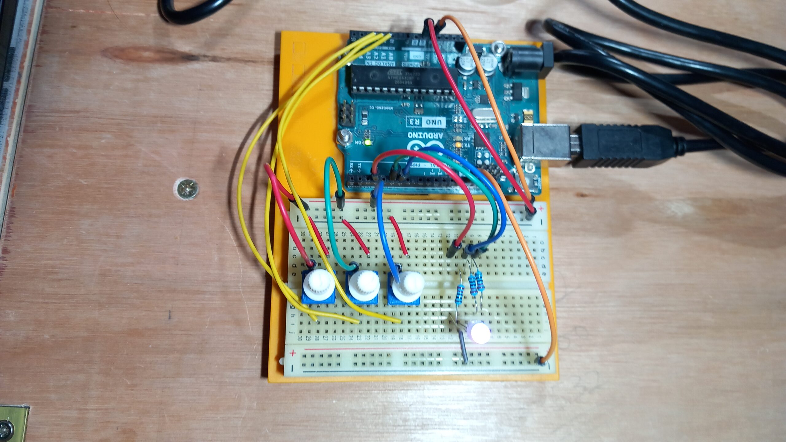
As an addition to the above, I decided to let the user change to colour in the LED with 3 potentiometers instead of entering numbers. Had to be careful to only use PWM pins to feed the LED. This worked out pretty well. As before the voltages read from the pots (0-1023 range) needed to be converted to the 0-255 range needed for the PWM pins.
24: Understanding Passive Buzzers
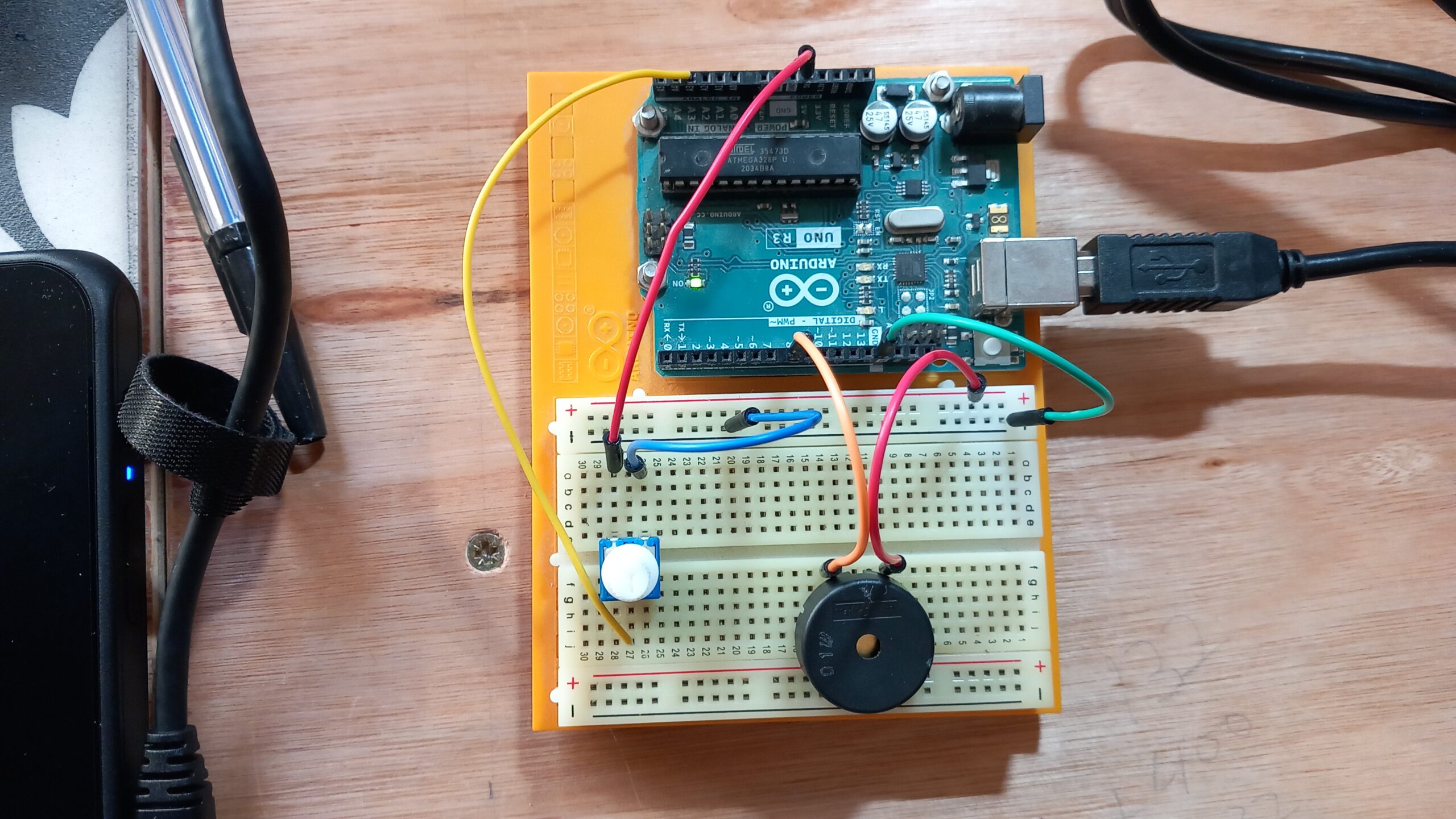
An interesting little challenge to get a passive buzzer to sound at different frequencies by altering the delay between switching it between HIGH and LOW states. This works differently to an active buzzer, where you can’t really alter the pitch easily.
A value for resistance of the potentiometer value is read by an analog in pin. This needs a bit of maths to do the conversion, as the larger the value from the pot (0 to 1023), the smaller the delay value (1000 to 100). Also this is measured in microseconds, so instead of delay() which can only do milliseconds, we need to use another command which uses microseconds – delayMicroseconds(buzzVal).
An interesting thing with this program was it wouldn’t work properly at first – even though the values being sent to the buzzer were right the sound was just a crackle. Eventually worked out the reason was that I was writing the values to the serial monitor as part of the main loop. Because we are dealing in Microseconds, the time it took to do that was enough to throw the sound off totally. I removed that code and it worked fine.
25: Understanding Photoresistors and Photo Detectors
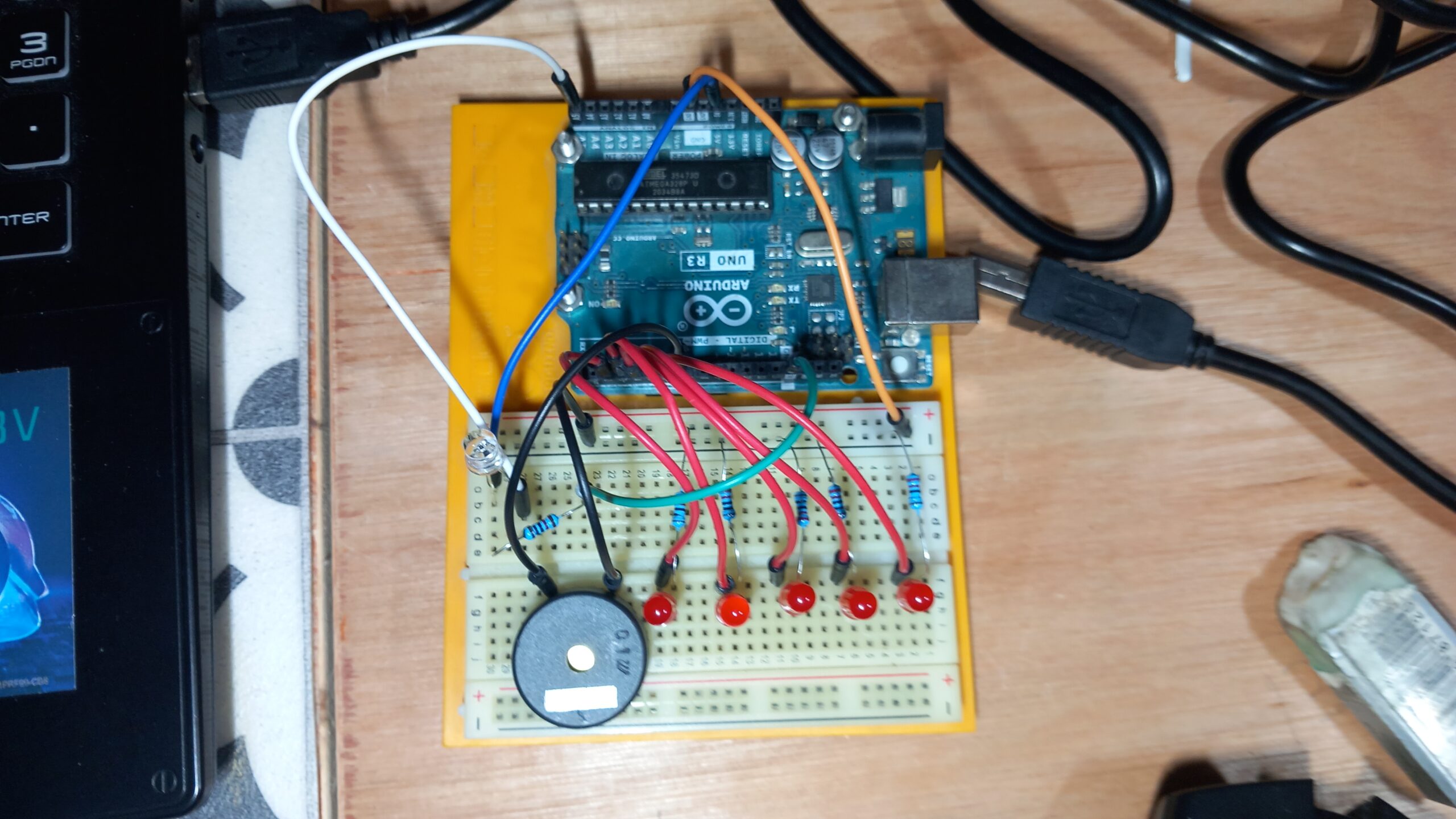
This one uses a photoresistor to detect the ambient light levels. To do this a 10K Ohm resistor is used in series with the photoresistor, and the voltage across that is measured. This is because it has a constant resistance so the voltage across it will change as the resistance of the photoresistor changes (you can’t measure current in the circuit, only voltage.) The analogRead read pin is connected between the negative end of the photoresistor and the 10K resistor. This effectively forms a simple voltage divider.
I added a strip of LEDs, more of which light up when the voltage reading is stronger (i.e. more light so less resistance produced) and a buzzer with the same code as 24. above, to make possibly the most awful sounding racket ever created, but the principle worked. A series of while statements in the loop handled switching the LEDs on and off according to a set of hard-coded values. The only thing is the code began to be very long with a lot of repeated code for each LED, so I wanted to work out how to tidy this up with functions to reduce the amount of code.
In the second version (25a) I condensed the LED lighting code into a function void(ledLighter) as follows:
void ledLighter(int state1, int state2, int state3, int state4, int state5) {
digitalWrite(led1, state1);
digitalWrite(led2, state2);
digitalWrite(led3, state3);
digitalWrite(led4, state4);
digitalWrite(led5, state5);
Serial.println(phoResistRead);
}
A similar set of conditionals in the loop fed the HIGH or LOW arguments to the function depending on the level of voltage read from the divider. This proved to be a lot trickier than I’d though, as it was difficult to pass the “LOW” and “HIGH” values as arguments into the parameters of the function. Got tied up in knots trying to declare them as strings first and was getting errors. Finally found out that the Arduino IDE just treats HIGH and LOW as constants, and sees them as equivalent to 1 and 0, so you can pass the actual words as urguments to the function and it knows what to do. Really good to know.
So now the code was more efficient and I had a nice little light meter indicator going. However I wanted to get the LEDs to fade in and out depending on the light levels, rather than switching on and off digitally, by using the PWM pins. This involved a few more variables and a bit more maths.
Version 25b had a variable lightRange, set to 1000 (ignoring the remaining 23 that could be detected to keep the number round), and had ledNumber, set to 5, to represent the number of LEDs. Dividing one into the other gave me ledBand, i.e. 200, which when divided into the total read voltage gives a number from 0 to 5, selecting one of 6 conditional states for the LEDs, telling the Arduino how many to light fully. To get the dimmable brightness, I got the remainder after dividing the read voltage by the 200. This was then converted from a scale of 0-200 to scale of 0-255 for the LED brightness, and the conditionals in the loop passed this value to the void(ledLighter) function. Works quite nicely and the fading LEDs are far more pleasing to see.
28: Using a Pushbutton as a Switch and as a Toggle Switch
This one introduced a few important topics. It consisted of a push button switch connected to 5v and an LED which it switches on and off. The circuit uses a high value (10K) resistor connected between the power supply and the switch. The voltage is read between this resistor and the switch to a digital read pin. This 10K is a pull up resistor and it forces the pin to read either a 1 or a 0, and not some in-between or floating value. When the button is held down it reads 0 and when it isn’t it reads 1. This is used for switches or for circuits requiring digital inputs. It could also be connected from the switch to ground, forming a pull-down resistor, in which case the read values would be reversed.
It was straight forward to have the LED switch on when the button was held down, and off when it was released. The second version was much trickier to code as it need to be a toggle switch. This meant having a separate variable, ledState, to be set to 1 or 0 depending on the current state of the LED. The loop detected any change in the button’s read value, from 1 to 0, and I wrote a separate function void toggle() which when it was called, read the current status of ledState, switched the LED to the opposite state and changed to value of ledState to reflect this. Where I got caught out ititially was by using 2 if statements in this function, both of which were executed, causing the LED to rapidly come on and off again. I needed to change this to an if, then an else if, so only one of them got used each time through the function.
30: Understanding Using Servos With a Photoresistor
In this circuit a servo is attached to 5v and ground, with a control pin fed by an analog write pin. Because the servo controls don’t come loaded with the basic Arduino package, a library must be imported first with #include <Servo.h> An instance of the servo class is called with Servo myServo; (not in the setup loop) then this is attached to the designated output pin with myServo.attach(servoPin);
Any commands sent to the servo now go through this servo object, so to move the motor to a position we do myServo.write(servoPosition); servoPosition being a number between 0 and 180 (degrees). So you could prompt this number from the user with the serial port.
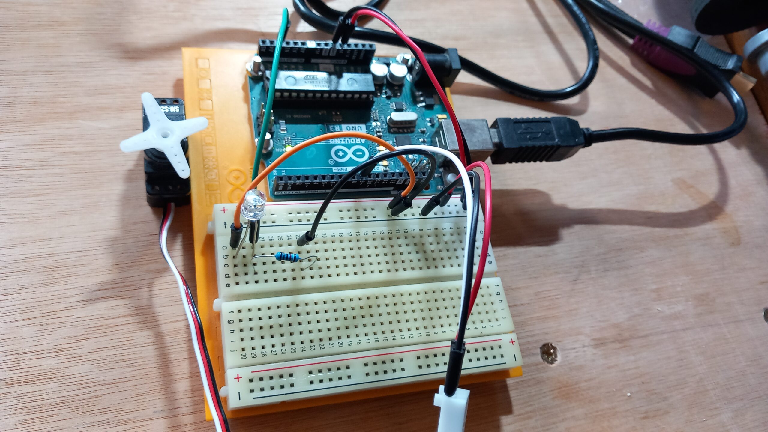
A nice exercise was to hook the servo up with a photoresistor and a voltage divider, like in number 25: above. This responded very nicely to the ambient light in the room, and with controlled lighting conditions could form a nice type of detector of people’s postion in an installation for example.
32: Understanding and Using Joysticks in a Project
This was a nice exercise combining the servo motors and a joystick, which is essentially just 2 potentiometers controlling the x and y axes, together with a digital switch. By attaching one servo to the other, it’s possible to get a full range of movement within basically an entire hemisphere. A very useful discovery was with the digital switch, where you would normally need to use a pull-up resistor, as in 28: above, if you set its output pin to HIGH the Arduino automatically seems to treat it as if there was a resistor there. Very handy.
